 "BiTurbo228 - Dr Frankenstein of Spitfires" (biturbo228)
05/17/2014 at 07:56 • Filed to: None
 0
0
 14
14
 "BiTurbo228 - Dr Frankenstein of Spitfires" (biturbo228)
05/17/2014 at 07:56 • Filed to: None |  0 0
|  14 14 |

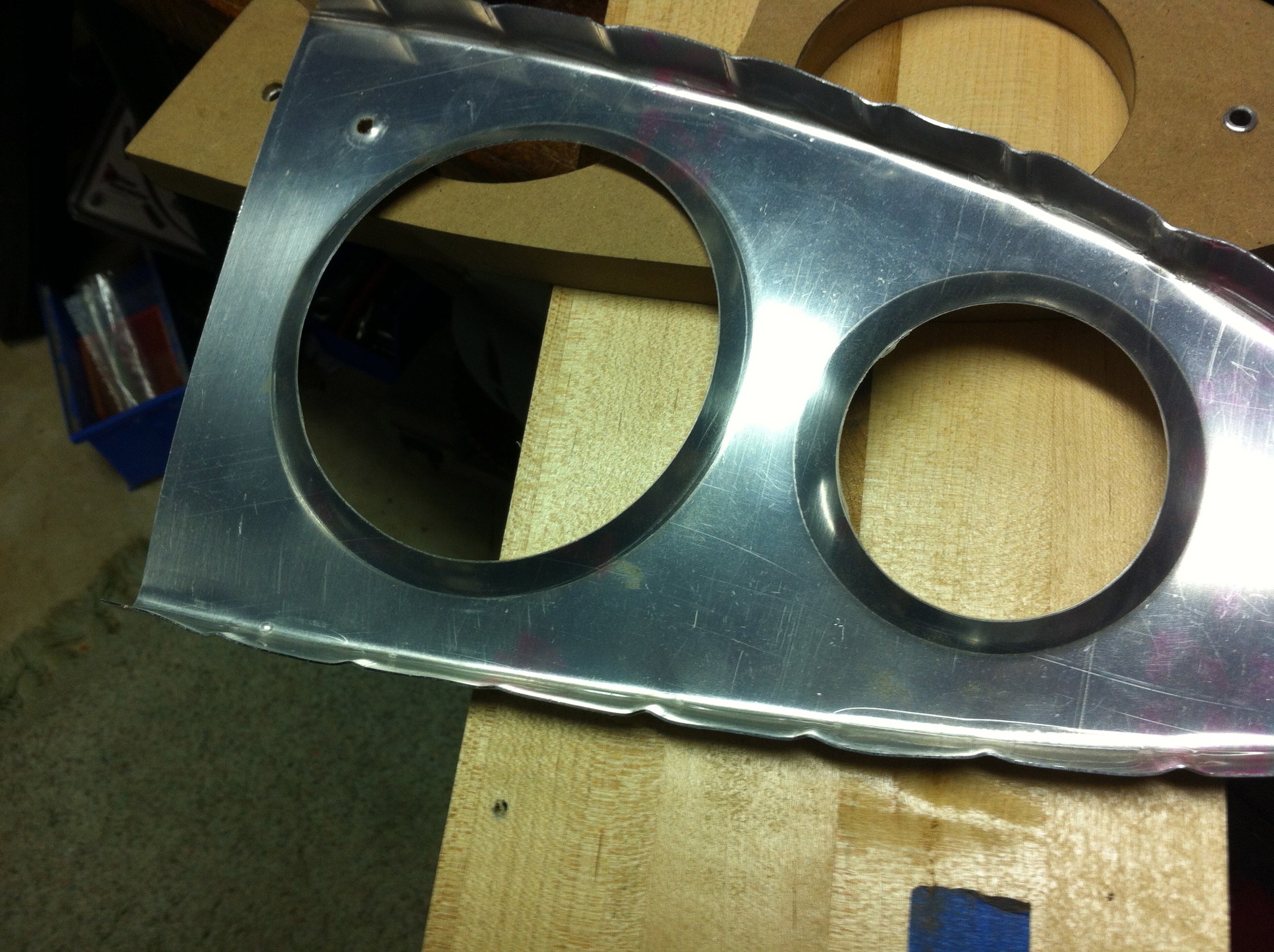
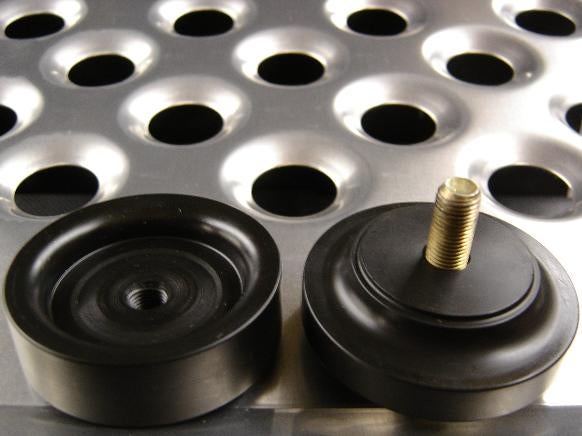
Edit: thanks CarlessCarGuy, it's a swage dimple tool. I've got plans to drill some holes to make lightweight bits for the Spitfire, but I don't know how you make the little lip around the inside of the hole for strength. Is there a special tool for making them? They look too neat to be hand-formed.
 IDROVEAPICKUPTRUCK
> BiTurbo228 - Dr Frankenstein of Spitfires
05/17/2014 at 08:01 |
|
It's probably a stamped piece. Probably the closest thing you could get would be drilling the hole and then putting the thing in a press and pressing into the holes with something with a rounded head but slightly larger diameter than your holes. the problem is rigging it up so that the whole thing doesn't flex and deform.
 Twingo Tamer - About to descend into project car hell.
> BiTurbo228 - Dr Frankenstein of Spitfires
05/17/2014 at 08:04 |
|
I'm sure I saw a specialist tool for stuff like this once, I'll googles and see if I can find it.
 Twingo Tamer - About to descend into project car hell.
> BiTurbo228 - Dr Frankenstein of Spitfires
05/17/2014 at 08:07 |
|
Found it, swage dimple tool, there are loads on ebay and specialist sites.

 BiTurbo228 - Dr Frankenstein of Spitfires
> Twingo Tamer - About to descend into project car hell.
05/17/2014 at 08:20 |
|
You legend, thanks :)
 Twingo Tamer - About to descend into project car hell.
> Twingo Tamer - About to descend into project car hell.
05/17/2014 at 08:30 |
|
No problem man, happy to help someone restoring a spitfire, love those.
 davedave1111
> BiTurbo228 - Dr Frankenstein of Spitfires
05/17/2014 at 08:44 |
|
What CarlessCarGuy said, but you can also make your own pretty easily with MDF and a couple of hole saws, and a nut-and-bolt to pull it all together. I've never done it in this context, and the holes were smaller but I once had to counter-sink screws into a thin brass sheet, and this was the easiest way.
 Bluecold
> BiTurbo228 - Dr Frankenstein of Spitfires
05/17/2014 at 10:04 |
|
The part does need strength too. I don't know what you're going to do to calculate that.
 BiTurbo228 - Dr Frankenstein of Spitfires
> Bluecold
05/17/2014 at 10:09 |
|
Very true, hopefully the flanges will help with that.
Even still, I won't be doing it on any existing structural bits. It's for any new brackets or gusseting that I'll make :)
 BiTurbo228 - Dr Frankenstein of Spitfires
> davedave1111
05/17/2014 at 10:11 |
|
Oh I see, so you'd cut a matching chamfer onto two blocks of MDF and then press them together. Shall do that if I need any larger holes cut :)
 Bluecold
> BiTurbo228 - Dr Frankenstein of Spitfires
05/17/2014 at 10:20 |
|
The flanges only help to increase the stiffness in the direction of the flange, not strength in the principal load direction. Now I wonder how hard it would be to get started with a copy of any CAD software you have pirated laying around.
 davedave1111
> BiTurbo228 - Dr Frankenstein of Spitfires
05/17/2014 at 10:25 |
|
Yeah, that's the one.
 BiTurbo228 - Dr Frankenstein of Spitfires
> Bluecold
05/17/2014 at 10:27 |
|
I have pretty much zero experience with CAD software, although I'd like to have a crack at it. My sister's boyfriend's company has access to a CAD milling machine and if I buy the materials I could make my own billet alloy parts for the Spitfire. That'd be neat.
I have a reasonable amount of experience with making panels stiff in the right directions, and from what I understand the circular flange would provide stiffness in most directions. Most likely more than the original flat sheet would.
 Bluecold
> BiTurbo228 - Dr Frankenstein of Spitfires
05/17/2014 at 10:35 |
|
I have a bit of experience with Catia (first year student course) and Solidworks (made one part in it to be 3d printed, using everything I remembered from the Catia course I took 3 years prior), and I'd say that you'll get the hang of drawing quite fast for simple parts after you get the hang of the term 'constraint'.
No idea about the stress calculations though. But I can't imagine that being too hard as long as you can assume an isotropic material. Or at least, it can't be too hard to at least get pretty pictures with a red and blue colormap indicating stress. Ensuring those pictures have any real-world meaning would be slightly harder. I do know that Catia's stress calculations are shit no matter what you do.
 BiTurbo228 - Dr Frankenstein of Spitfires
> Bluecold
05/17/2014 at 11:37 |
|
Ah, the image of the pretty red and blue colourmap has reminded me that I have a friend who's done a few virtual stress calculations in her materials science degree. She modeled a Formula Ford rear suspension subframe for one of her assignments. Perhaps if I ply her with wine she'll give me a quick tutorial :)